Su carrito de compras está vacío
 
English Polski Spanish 
Buscar un manual
 

(p.Ej. AA-V20EG JVC, ZX-7 Sony)
PayPal 1000+ rating Secure, Encrypted Checkout.
 
Usuarios conectados
Actualmente hay 5499 visitantes online.
Productos
Información
Destacado
Inicio >> AIWA >> ZL500 Manual de Servicio
 
 0 artículo(s) en Su carrito 

AIWA ZL500
Manual de Servicio


¡Twitee acerca de este producto y obtenga $1.00 de crédito en la tienda para uso!
  • Contiene diagramas del circuito
  • Descargable
  • Formato PDF
  • Manual completo
  • Idiomas: English
Precio: $4.99

Descripción del AIWA ZL500 Manual de Servicio

Manual de servicio completo en formato digital (archivo PDF). Los manuales de servicio por lo general contienen diagramas de circuitos, tarjetas de circuitos impresos, consejos para reparación, diagramas de cableado, diagramas de bloque y lista de refacciones. El Manual de Servicio (a veces llamado Manual de Reparación) es usado principalmente por los técnicos.

Si tan solo quiere saber cómo utilizar su televisión, reproductor de vídeo, reproductor de mp3, etc. Quizá lo que necesita es el Manual del Propietario. Después de colocar la orden le enviaremos las instrucciones de descarga a su dirección de e-mail.

The manual is available in languages: English

Not yet ready
You must purchase it first

Opiniones de los clientes
No hay comentarios de productos.

TEXT_PDF_SNIPPET
In such a case, check also if the POWER AMPLIFIER circuit or power supply circuit has any abnormalities or not.

2-2. Regarding reset
There are cases that the machine does not work correctly because the MICROCOMPUTER is not reset even though the AC power cord is re-inserted, or the software reset (pressing the STOP key + POWER key) is performed. When the above described phenomenon occurs, it can lead to wrong judgement as if the MICROCOMPUTER is defective and to exchange the MICROCOMPUTER. In such a case, perform the forced-reset by the following procedure and check good or no good of the MICROCOMPUTER. 1 Remove the AC power cord.

R O

M I C

P U

O M

R

FRONT C.B

C
18 15

T E

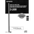
% VSS C113 MICROCOMPUTER * VDD C113

FRONT C.B Short with tweezers.

Fig-2-2

2 Short both ends of the electrolytic capacitor C113 that is connected to VDD of the MICROCOMPUTER with tweezers. 3 Connect the AC power cord again. If the MICROCOMPUTER returns to the normal operation, the MICROCOMPUTER is good. Note: The reference number or MICROCOMPUTER pin number of transistor (Q110) and electrolytic capacitor (C113) can change depending on the models. Be sure to check the reference numbers on schematic diagram before starting the discharging work.

2-3. Confirmation of soldering state of MICROCOMPUTER
Check the soldering state of the MICROCOMPUTER in addition to the above described procedures. Be sure to exchange the MICROCOMPUTER after surely confirming that the trouble is not caused by poor soldering but the MICROCOMPUTER itself.

�5�

Quizás también quiera comprar

$4.99

ZL500 AIWA
Manual de Usuario

Manual del propietario completo en formato digital. El manual estará disponible para descarga como …
>
Parse Time: 0.179 - Number of Queries: 101 - Query Time: 0.05