|
No hay comentarios de productos.
ELECTRICAL ADJUSTMENT -2/5
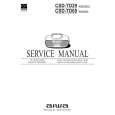
<MW/LW Adjustment> Make the following preparation for MW/LW adjustment. Preparation � Measuring instruments: Standard Signal Generator (S.S.G)/Loop antenna/Oscilloscope/Millivoltmeter 1) Connect the unit and measuring instruments as shown in the diagram below. 2) Position the loop antenna connected to S.S.G. and the one connected to the unit 60cm apart.
60cm AC MILLIVOLTMETER OSCILLOSCOPE
Standerd Signal Genertaor
CH1 CH 2 OUTPUT CH1 CH2
SET
HP OUT(L) HP OUT(R)
4. IF Adjustment Requirement: � Test point: HP OUT � Adjustment location: L006 1) Set S.S.G. to AM, carrier of 1404KHz with 30% modulation, and source at 1KHz. 2) Tune the receiving frequency of the unit at MW 1404KHz. 3) While monitoring the waveform at 1KHz through the oscilloscope, lower the output level of S.S.G. maximum (till a certain degree of noise is monitored). 4) Adjust L006 so that the millivoltmeter points maximum. 5. MW Tracking Adjustment Requirement: � Test point: HP OUT � Adjustment locations: L003(BAR-ANT), TC001 1) Adjust TC001 so that the mechanical center. 2) Set S.S.G. to AM, carrier 603KHz with 30% modulation, source at 1KHz, and output at maximum. 3) Tune the unit to the receiving frequency at MW 603KHz. 4) While monitoring the waveform at 1KHz through the oscilloscope, lower the output level of S.S.G. maximum (till a certain degree or noise is monitored). 5) Adjust L003(BAR-ANT) so that the millivoltmeter indicates maximum. 6) Set S.S.G. to AM, carrier 1404KHz with 30% modulation, source at 1KHz. 7) Turn the unit to the receiving frequency at MW 1404KHz. 8) While monitoring the waveform at 1KHz through the oscilloscope, lower the output level of S.S.G. maximum (till a certain degree or noise is monitored). 9) Adjust TC001 so that the millivoltmeter indicates maximum. 10) Repeat the above step 2 to 9 two to three time.
-30-
|